Railguns
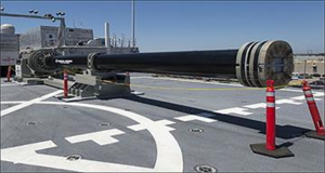
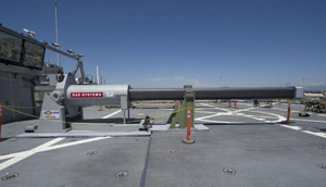
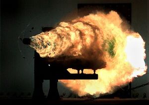
You have probably heard of railguns. They are commonly depicted as some kind of fancy high-tech gun that can shoot its bullets really, really fast. But what are they, really? And what can they actually do? Well, let's find out!
Fundamentally, a railgun is a projectile weapon that uses the magnetic forces of high electric currents to push a projectile between two rails. And yes, this does potentially let the railgun shoot out stuff that goes very fast. And because it only uses electricity, you can get away from funky chemistry stuff like powders and primers. But the high speed has the side effect of lots of rail wear. You also need to store large amounts of energy, and then shape that energy to produce pulses of extreme currents. And the magnetic energy stored in the rails limits the efficiency of railguns compared to some other kinds of launch systems.
A railgun is a kind of electromagnetic gun, and has the various properties common to electromagnetic guns. Of all the electromagnetic guns, it is the most mature technology, with many research projects that have progressively made railguns more and more capable. There are several efforts now underway among various nations (as of 2024) to build fieldable railguns. Railguns are also the best known of the electromagnetic guns, and have appeared in many works of fiction. And their simplicity makes them one of the easiest electromagnetc guns to understand how they work.
Working principles
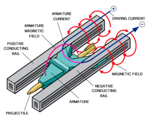
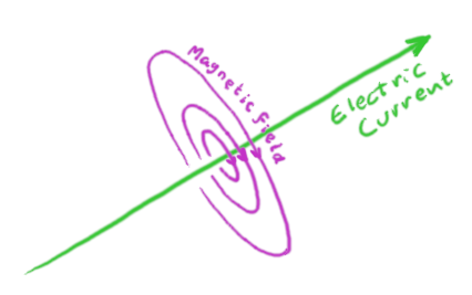
An electric current creates a magnetic field that circulates around it. If you have two parallel conductors carrying current in opposite directions, they both produce a field that points in the same direction between them, amplifying the field in that direction (likewise, outside the two wires the fields point in opposite directions making the field weaker there and causing it to fall off faster than the field from a single wire).
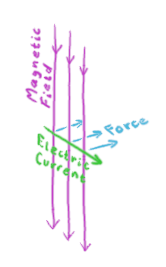
A magnetic field exerts a force on any electric currents going through it. The force is in the a direction perpendicular to both the magnetic field and the current, and is proportional to both.
|
The magnetic field (magenta) circulating around a cross sectional plane perpendicular to the direction of an infinite line of current (green). |
The magnetic field (magenta) circulating around a cross sectional plane perpendicular to the direction of two infinite line of current in the opposite directions (green). |
The force on a current due to a magnetic field. |
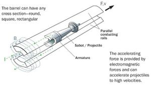
The basic idea for building a railgun is to take two parallel conductive rails. Short the two rails with a conductive projectile near the breach. Apply a pulse of very high current, that will run down one rail, through the projectile, and back up the other rail. The current-carrying parts of the rail make a high magnetic field between them. This field pushes on the current flowing through the projectile, which launches it down the rail. As long as the projectile shorts the two rails, it experiences the force and is accelerated faster.
The magnetic field can be enhanced if the railgun uses a ferromagnetic barrel around its rails. This in turn will increase the force on the projectile and improve the railgun efficiency and performance. However, for most practical applications (including weapons use), the field between the rails is far above the saturation field of any known ferromagnet, such that using a ferromagnet only serves to decrease the efficiency.
The overarching requirement of extreme currents to provide both the magnetic field and propulsive force combined with a largely low resistance design using highly conductive rails and a projectile mean that railguns are engineered to be extremely high current but relatively modest voltage devices. The currents regularly reach hundreds of kiloamperes (kA) to megaamperes (MA) with voltages in the low kilovolts (kV) [1][2][3].
Sadly, a railgun generally will not crackle with electric arcs when it is charging up. These arcs would short the circuit between the rails, drawing power without any benefit and preventing current from getting to the projectile.
The projectile
A railgun projectile will need to make good electrical contact with the rails as it slides. It will also need to have good aerodynamic properties and terminal performance. Because these two requirements are often at odds, a common design for high speed railguns is to use a light-weight conductive sabot, often made of aluminum (carbon fiber has also been proposed). The sabot holds the projectile while maintaining electrical contact, and is the actual thing being pushed. Once the sabot leaves the rails, it falls away to allow the projectile to continue down-range in free flight.

|
| BAE Systems railgun hypervelocity projectile, with (left) and without (right) its sabot. |
| 
|
| Some designs for railgun rails, sabots, and projectiles. | |
|
| The sabot separates from a hypervelocity railgun dart immediately after launch. |
Because the sabot leaves with the same speed as the primary projectile, and can often have a non-negligible mass, there is a risk of the sabot traveling down-range for some distance and causing unintended damage.
It is common for railgun projectiles to be long, aerodynamic darts with fins for stabilization and possibly guidance. Because they are often designed to be shot at hypersonic speeds, they will often take the form of a long-rod penetrator, like an anti-tank APFSDS shot. For these hypersonic rounds, the kinetic energy of the round is likely to be larger than the chemical energy released by any explosive warhead, and consequently they are likely to forgo a warhead and let the energy of their impact do their exploding for them. However, there are other options that have been considered. For example, shrapnel rounds where the projectile is fused to release a swarm of small sub-projectiles (generally made of a dense material such as tungsten) have been designed and may be useful for defense against drones, missiles, and aircraft.

|
| A bursting charge disperses shrapnel sub-projectiles in a test of a railgun hypervelocity projectile. |
Developing guidance that can withstand the high acceleration, intense magnetic field, and plasma environment of a railgun launch can be challenging. However, it is a challenge that has been solved at least once[4].
Basic electrical engineering and interior ballistics of a railgun
Warning! This section is going to have a lot of (gasp) math! If you don't like math, the highlights are that the efficiency of a railgun probably won't be all that great but can be made not horribly terrible either, and there might be ways to make it better. And now you can skip to the next section if you want. But if engineering of extreme propulsive systems is the kind of thing that you think is fun, read on!
This section will illustrate the basic physical mechanisms behind the operation of a railgun, using as an example a railgun operated under the most basic possible conditions – namely constant current supplied at the breach. Actual systems are likely to be more complicated than this, but from the principles introduced here you can appreciate some of the main engineering factors that go in to railgun design.
Electrical forces
The mechanics of a system of electric currents, its energy, and the forces acting on it, are often most conveniently found using the inductance of the system, commonly denoted . For our purposes, the inductance per unit length will be more convenient. The actual inductance of a particular circuit will likely be computable only numerically, but we can make some useful approximations. The DC inductance per unit length of a transmission line of radius with wire separation is known to be[5]
where H/m is the permeability of free space. The rails in our railgun approximate this transmission line between the power couplings at the breach and the location of the projectile. While the rails might not be circular in cross section, we can still take to be some approximate characteristic transverse length scale of the rail cross section (perhaps for rectangular rails of height and width ; the logarithmic dependence means the net result is not strongly dependent on the exact value for ). If the rails are enclosed in a permeable material (such as iron or other ferromagnetic substance), can be approximately replaced by the permeability of the material as long as the current is not so strong as to produce a magnetic field which saturates the material.
The electric force on the projectile with constant current is
The approximate magnetic field between the rails can be found by using the force on a current carrying wire (in this case the projectile) in a uniform magnetic field
where is the average magnetic field over the projectile. If is not significantly smaller than the saturation field of the permeable material of the barrel used to amplify the field, the material is likely to show the effects of saturation and the approximation of replacing by will no longer hold.
For the projectile at a distance , the total inductance is . The work done on the projectile plus sabot is the product of the force and the distance over which that force is applied; . The magnetic energy of a circuit is . The total energy is , with the result that, ignoring any other losses, the efficiency of a railgun with constant current fed into the rails only at the breach is never greater than 50%.
For a total rail length , when the projectile leaves the railgun so that the final work done on the projectile and sabot, ignoring losses, and the final magnetic energy are
Frictional forces
In addition to inefficiencies due to the loss of magnetic energy once the projectile leaves the barrel and the circuit is broken, there will be frictional and resistance losses. Contact with the rails will produce a frictional force on the projectile. The work done by the force against this friction over the entire length of the rails is
The kinetic energy of the projectile plus sabot will be the electrical work done on the projectile minus the amount of that work that goes into friction, such that
The kinetic energy of the projectile alone is
where is the fraction of the mass of the projectile to the total projectile + sabot mass.
The projectile speed will be
where is the projectile mass.
Resistive losses
If the projectile has a resistance and the rails have a resistance per unit length , the total resistance of the system when the projectile is at a distance from the breach will be
The resistive power loss is
Under constant force, the position as a function of time is
for projectile mass The time to reach the end of the rails is thus
If we integrate the resistive power over time to find the total resistive energy loss,
where is the resistive energy dissipated across the projectile
and is the resistive energy dissipated into the rails
Efficiency
The total efficiency therefore becomes
More sophisticated design can increase the efficiency, at the expense of increased complexity. For example, multiple energy storage units distributed along the rails that are triggered as the projectile passes would reduce the stored magnetic energy in the rails at the time the projectile leaves. However, discussing the engineering of these more complicated systems is beyond the scope of this work. In addition, the additional complexity such a system would incur reduces the railgun's attractiveness compared to coilguns, which have similar timing and switching considerations but also can eliminate the rail friction by using a levitated projectile.
An alternative method to increase the efficiency is to violate the assumption that the current is constant during the projectile acceleration. If the current is decreased as the projectile travels down the barrel, the magnetic energy in the barrel likewise decreases. In the limit of a sudden current pulse when the projectile is at the breach and then allowing the current to only be maintained by magnetic induction thereafter, without additional energy input into the railgun, has an interesting similarity to a gunpowder weapon where the hot powder is only at its maximum pressure when the bullet is near the breach and the pressure falls off with distance as the powder gases do work on the bullet. In this case, neglecting resistance, the magnetic flux through the circuit is kept constant by induction and the current falls off in inverse proportion to the distance the projectile has traveled down the rails
Another natural solution is to deliver a constant power to the railgun instead of a constant current. As we have seen, the electrical work and the magnetic energy are both proportional to the position of the projectile down the barrel. However, as the projectile speed increases the position changes faster and faster and more and more energy must be added in a given time. If the power supply has a maximum power available, once the railgun is operating at that power the current will start to decrease with time to both reduce the rate of work on the projectile and the rate of increase in magnetic energy.
Again, the full analysis of the problem with a time-varying current is beyond the scope of this article although the work done here should be a good start for anyone interested in working it out for themselves.
Finally, it may be possible to recover some of the magnetic energy for later use. Perhaps this energy could be used to charge a capacitor near or at the end of the firing cycle, which would then provide some of the energy for the next shot.
For real high powered experimental railguns, efficiencies range from 4%[1] to 35%[2]. Sliding contact armatures tend to have significantly better efficiency than plasma armatures (see below). Energy recovery of the magnetic energy to charging the launch capacitors can allow efficiency to exceed 50%[2].
Self forces
The same interaction between the magnetic field and the current that pushes the projectile also acts on the current flowing through the rails. This produces a strong force that acts to push the rails apart[2]. If this happens, electrical contact with the projectile will be broken and the rails might get permanently damaged if they are warped beyond their elastic limit. A consequence of this is that railguns will not have bare exposed rails. Instead, the rails will be contained within a strong barrel structure that can support the forces pushing on the rails to minimize strain on the rails and keep the gun from bursting or warping. Sadly, common artistic interpretations of railguns with a pair of exposed unsupported rails will not work.
If you are using the engineering analysis from above, the force per unit length pushing the rails apart is
Recoil
The fact that electromagnetic guns have recoil was discussed in the parent article on electromagnetic guns. In the implementation of the railgun in particular, the circuit containing the current in the rails and projectile must be closed on the other end of the current loop. The magnetic forces push on this just as much as they do on the projectile, producing recoil[6] in accordance with Newton's second law of motion.
Rail durability
In order to maintain electrical contact with the rails the projectile must either keep a sliding physical contact with the rails or strike an electric arc to the rails. An electric arc is arguably the worse of the two options, as each shot will be arc-welding the rails and will produce ablation and excessive rail wear[1]. A sliding contact is no worse than any conventional firearm with the bullet maintaining a sliding pressure seal with the barrel. But as speeds get higher and higher, a sliding contact produces more and more barrel wear. A high speed projectile can be expected to significantly reduce rail life compared to the barrel life of a modern firearm. With that said, it is difficult to fully eliminate arcing during railgun operation[7], with additional wear occurring both near the breach and at the muzzle[2]. The U.S. Navy railgun has reported rails lasting for several hundred shots at speeds of 2 km/s[8]. This is within the speeds achieved by some tank main guns. It is not clear how well rails can stand up to projectiles shooting through them at speeds significantly larger than this.
Muzzle Flash
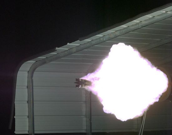
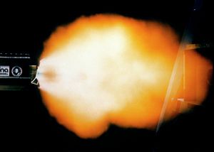
High speed wear on the rails and projectile will produce vaporized material that are ejected from the barrel on launch. In addition, magnetic energy left in the electrical system as the projectile leaves the rails will be discharged as an electric arc. Both of these processes act to produce a loud muzzle blast and muzzle flash. Much like modern firearms, this will indicate to observers that the weapon was fired and can help to localize its location, either directly by the flash or from dust and debris kicked up by the blast.
Upper limits to speed
As current flows through the projectile, electrical resistance will heat it up. Thus, some fraction of the energy delivered for the discharge will go into raising the temperature of the projectile. At high enough speeds, this inefficiency will deposit so much heat that the projectile will be affected, either warping, partially or fully melting, or vaporizing. Warping or partial melting will adversely affect accuracy, complete melting or vaporization will prevent the projectile from reaching its target. Using the terminology of the electrical engineering and interior ballistics section, above, the maximum speed is given when the resistive energy dissipated across the projectile exceeds the heat energy needed to damage the projectile to the point that it no longer functions. One estimate[9] gives a maximum speed for monolithic solid dumb projectiles of around 20 km/s; and perhaps as low as 2 km/s for projectiles containing sophisticated equipment such as guidance, control systems, or after-launch propulsion.
Variations on the standard railgun design
Augmented railguns
If you add additional current-carrying rails adjacent to the rails that guide the projectile, this will increase the magnetic field the projectile experiences. In fact, if the augmenting rails go all the way to the muzzle where they loop over or under to connect with their counterpart without getting shorted by the projectile, they provide a more uniform field which is a factor of 2 more effective at accelerating a given current through the projectile with the same current through the rails. This all allows the projectile to conduct less current for the same acceleration, lessening the issues with arcing and rail erosion.
Segmented railguns
One of the limits to efficiency of the railgun is that magnetic energy is stored throughout the rail that the projectile has passed through. One potential solution is to break the rails up into electrically independent sections and energize each pair of rails only when the projectile is in them. In principle, this could reduce the stored magnetic energy and increase the efficiency. One known problem is the difficulty of getting the projectile to transition smoothly from one set of rails to the next.
Plasma armature railguns
So you want to get your projectile even faster? There's a method for that. Instead of having current go through the sabot to push the projectile, strike an arc at the back of an insulating projectile (often by flash-arcing across a thin conductive foil or ribbon) and have the plasma from the arc push the projectile[10]. This seemingly crazy idea has resulted in railguns that shoot out their projectile at 6 km/s or more, with the highest speeds attained with projectiles made of low atomic weight and low heat of vaporization (such as many plastics)[11] – although a rear plastic plug might be used to accelerate a denser projectile in front of it. However, if you thought that normal railguns were hard on the rails they have nothing on plasma railguns! The plasma arc continually erodes the rails at a high rate, with continual ablation leading to even more plasma. The final speed of the projectile from one of these things can be rather unpredictable – a major limit happens when a second arc is struck in the vaporized debris trail some distance behind the projectile, and this arc sucks out most of the current but does not do much pushing. Exactly when this restrike phenomenon happens in the turbulent sparsely ionized debris is variable, hence the unpredictability. Reference [11] suggests that reliable speeds in excess of 6 to 8 km/s cannot be achieved without controlling restrike (although referencing one test that achieved 10 km/s), but suggests several methods by which restrike may be avoided, controlled, or mitigated. Namely:
- Segmented railguns, with separate independent power supplies feeding sections of rails insulated from the other sections every 1 to 2 meters.
- Adding special coatings that increase the breakdown voltage of the vapor evaporated and ablated from the rails and the back of the projectile, with the note that the practical problems of renewing this coating would probably limit the technique to laboratory devices.
- Injecting high speed neutral gas into the gun (at which point you might question why you are using a railgun anyway, rather than a light gas gun).
- Reducing the power dissipated by the armature, by reducing the delivered voltage or current.
- Improved materials, with a synthetic diamond coating suggested as optimal.
It is suggested that these techniques may allow speeds in the 10 to 20 km/s range with the main limit on speed now being viscous drag on the armature plasma.
At these speeds, projectiles will not survive long in an Earth-like atmosphere, flying maybe 30 to 150 times their length in sea level air before being fully eroded away. They may be useful in exo-atmospheric combat, particularly in setting featuring relatively low performance rocket thrusters where the railgun slugs cannot simply be outrun.
Not all plasma armature railguns are used at extreme speed, with some experimental railguns designed with plasma armatures with design goals of approximately 2 km/s projectile speeds[1]. However, sliding contact designs offer significantly improved efficiency and barrel lifetime at these lower speeds[2].
Plasma railguns
Want something even crazier than making the armature out of plasma? What if you make the projectile out of plasma, too. Now we have a plasma railgun, designed to launch puffs of plasma, or even plasmoids, at ridiculous speeds – one study[12][13] launched plasmoids of roughly a milligram in mass at speeds of several hundred km/s. This is, in fact, an attempt to make a plasma gun, and they don't work well as weapons for all the reasons described for normal plasma guns. Suggested uses for such things are "fast opening switches, x-radiation production, radio frequency (rf) compression, as well as charge-neutral ion beam and inertial confinement fusion studies"[13].
Plasma rails
What happens if you go even farther, and make the rails themselves out of plasma? Well, mostly they immediately dissipate and don't work. The only reason we're bringing this up here is that some popular science fiction media has depicted railgun fire with what are described in lore as extended plasma rails jetting from the end of the barrel. As you by now know from reading the above material and the plasma gun article, any such rails would simultaneously disperse, explode away from each other at high speed by the magnetic self-forces, and short themselves out before the current could get to the projectile. They may look neat, but are not realistic.
Rocket railguns
One suggestion to get around the projectile heating problem for high speed launches is for the projectile to carry its own expendable coolant with it[9]. As the projectile is accelerated and heats up, the coolant absorbs that heat and evaporates, making a high pressure vapor that shoots out a nozzle at the back. This escaping coolant then acts like a rocket, pushing the projectile even faster. As the vapors pass through the magnetic field at high speed, they are ionized, which allows an electric arc to strike behind the projectile. Now, the mechanisms of the plasma armature railgun also come in to play, with the ionized vapor being accelerated up into the projectile, pushing it even faster down the barrel. It is estimated that speeds of a few hundred km/s could be attained in this fashion, although no tests of the mechanism have been conducted.
Credit
Author: Luke Campbell
References
- ↑ 1.0 1.1 1.2 1.3 S. G. Tatake, K. J. Daniel, K. R. Rao, A. A. Ghosh, and I. I. Khan, "Railgun", Defense Science Journal, Vol 44, No 3, July 1994, pp 257-262 https://web.archive.org/web/20171111205554/http://publications.drdo.gov.in/ojs/index.php/dsj/article/view/4179/2439
- ↑ 2.0 2.1 2.2 2.3 2.4 2.5 A. E. Zielinski, M. D. Werst, J. R. Kitzmiller, "Rapid Fire Railgun For The Cannon Caliber Electromagnetic Gun System", 8th Electromagnetic Launch Symposium, April 1997 https://repositories.lib.utexas.edu/items/6e9f0b8e-2e21-4bba-a42d-c4e664af0e1b , A. E. Zielinski and M. D. Werst, "Cannon Caliber Electromagnetic Launcher", IEEE Transactions on Magnetics, Vol. 33, No. 1, January 1997, pages 630-635 DOI: 10.1109/20.560087 Bibcode:1997ITM....33..630Z.
- ↑ Spencer Ackerman, "Video: Navy’s Mach 8 Railgun Obliterates Record", Wired, December 10, 2010 https://web.archive.org/web/20140111212221/http://www.wired.com/dangerroom/2010/12/video-navys-mach-8-railgun-obliterates-record/
- ↑ https://www.baesystems.com/en-media/uploadFile/20210404062224/1434555443512.pdf
- ↑ J. D. Jackson, "Classical Electrodynamics, Second Edition", John Wiley & Sons, New York (1975)
- ↑ Wm. F. Weldon, M. D. Driga, and H. H. Woodson, "Recoil in electromagnetic railguns", IEEE Transactions on Magnetics, Vol. MAG-22, No. 6, November 1986, pp 1808-1811, Bibcode: 1986ITM....22.1808W DOI: 10.1109/TMAG.1986.1064733
- ↑ Michael Fisher, "Hypervelocity Projectiles: A Technology Assessment", Defense Systems Information Analysis Center, November 2, 2019, https://dsiac.org/articles/hypervelocity-projectiles-a-technology-assessment/
- ↑ Sydney J. Freedberg Jr. "Navy Railgun Ramps Up in Test Shots", Breaking Defense, May 19, 2017, https://breakingdefense.com/2017/05/navy-railgun-ramps-up-in-test-shots/
- ↑ 9.0 9.1 F. Winterberg, "The electromagnetic rocket gun", Acta Astronautica Vol. 12, No. 3, pp. 155-161, 1985
- ↑ S. C. Rashleigh and R. A. Marshall, "Electromagnetic acceleration of macroparticles to high velocities", Journal of Applied Physics 49, 2540-2542 (1978)
- ↑ 11.0 11.1 J. V. Parker, "Why plasma armature railguns don't work (and what can be done about it)", IEEE Transactions on Magnetics, Vol. 25, No. 1, pages 418-424, January 1989
- ↑ Sovinec, C. R. (1990). "Phase 1b MARAUDER computer simulations". IEEE International Conference on Plasma Science. 22 (16). https://inis.iaea.org/search/searchsinglerecord.aspx?recordsFor=SingleRecord&RN=22057516
- ↑ 13.0 13.1 Dengan, J. H.; et al. (1 August 1993). "Compact toroid formation, compression, and acceleration". Physics of Fluids B. 5 (8): 2938–2958. Bibcode:1993PhFlB...5.2938D doi:10.1063/1.860681



![{\displaystyle {\mathcal {L}}={\frac {\mu _{0}}{2\pi }}\left({\frac {1}{2}}+\ln \left[{\frac {d}{r}}\right]\right)}](https://wikimedia.org/api/rest_v1/media/math/render/svg/01766da5195df05d3e6fb71cd0a3147e0dcec99a)


